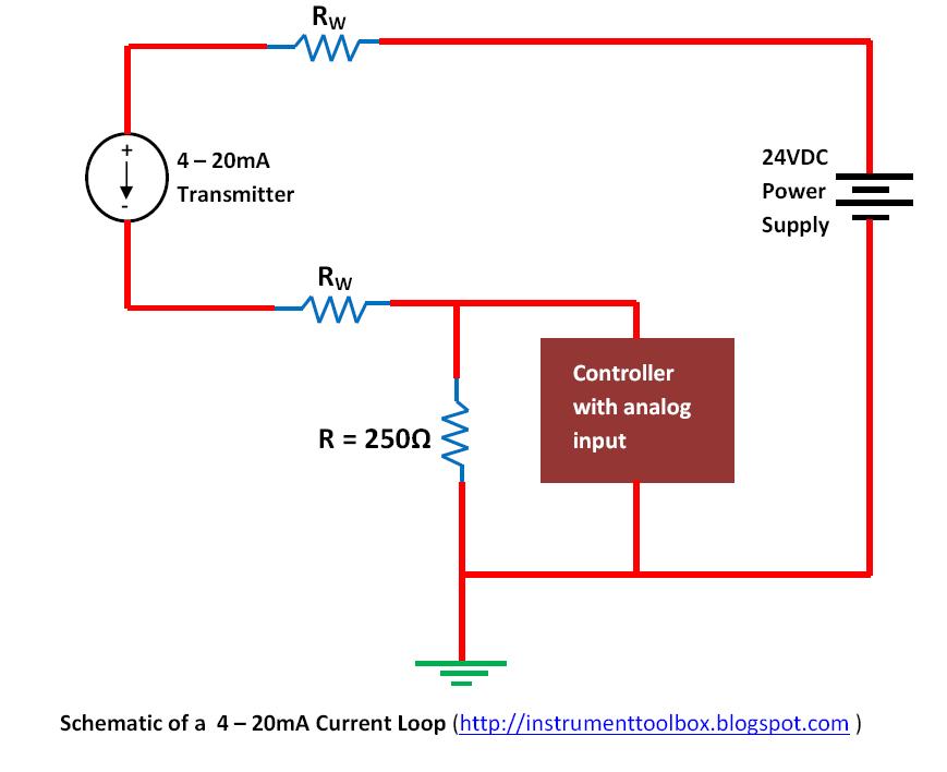
4 20ma Loop Powered Wiring Diagram
20ma wiring transmitter wire control instrumentation wires Loop 20ma fundamentals fuse Fundamentals, system design, and setup for the 4 to 20 ma current loop
Fundamentals, System Design, and Setup for the 4 to 20 mA Current Loop
20ma loop ma current 20 signal system ni fundamentals control data setup wire transducer using transmit instrumentation instruments 4-20 ma current loop 20ma loop ma current 20 signal system ni power fundamentals sensor setup supply isolated data control wire transducer io characteristics
Basics of the 4
20ma wiring transmitter signal output resistor parallel configurationFundamentals, system design, and setup for the 4 to 20 ma current loop 4 to 20ma wiring diagram.
.


4-20 mA Current Loop | Basic Fundamentals

Basics of The 4 - 20mA Current Loop ~ Learning Instrumentation And

Fundamentals, System Design, and Setup for the 4 to 20 mA Current Loop - NI

Fundamentals, System Design, and Setup for the 4 to 20 mA Current Loop